Initially RealCADD will open with a new Plan – "Untitled 1" – which will be displayed at the bottom of the Window menu. As more drawings are opened, they will add to the list. To move from one to another, simply click the one you want. The current drawing will be ticked.
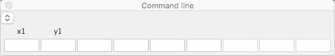 The Carbon version of RealCADD Command Line pallet is shown to the right. The Cocoa version Command line is similar, but it is fixed to the bottom left of the window instead of being a floating pallet.
 The principle behind the command line is that you can enter data for objects (line, oval, rectangle etc.) as you draw, rather than editing the data after the object is drawn. Clicking the
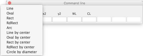
 ![]() arrows will display the menu of objects that can be drawn with the command line.
arrows will display the menu of objects that can be drawn with the command line.
To see details of how the tools work in the command line, click the appropriate menu item in the image to the right and scroll down. The descriptions are based on the standard Mac Click & Drag drawing mode. If you have selected Click & Click in Preferences, then there will be minor differences.
The basic operation of the command line (having selected it in the Window menu) is to start drawing with whatever cmd you wish to use and, while holding the mouse button down, enter the specific data in the command line window, tabbing from one box to the next. When you are done entering data, hit the ⏎ (Enter/Return) key and let go the mouse. The object will be draw according to the data you have entered. You can use some Snap attractions (End, Center and Intersection) to select a start point for drawing the object. Currently you can't use Perpendicular or Tangent (if drawing a line).
RdRect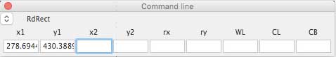 With the command line active, selecting the RdRect tool will automatically change the command line pallet to rounded rectangle mode.
Click on the drawing where you want to start your rounded rectangle, keep the mouse button held down and start to drag. The pallet will automatically register x1 and y1 (the start position of the rounded rectangle), where you clicked.
Once you have started to drag, you can select the entry mode.
X-mode
If this is the first time you have used the command line the pallet will probably be in this mode and will show the next two boxes as x2 and y2 as image above right. These will be the absolute x and y positions of the diagonally opposite corner of the rounded rectangle.
If it is not in this mode hit the X key, which will put it in X-mode.
To complete drawing your rounded rectangle, enter the x2 position data (keeping the mouse button held down); hit the ⇥ (tab) key to move to the y2 box and enter the y2 position data. Click ⏎ (Enter/Return) and let go the mouse.
The next two boxes are optional. rx is the x-radius of the corners: enter the radius you want. ry is y-radius of the corners: enter the radius you want. If you want the same x and y radii, enter the x-radius and hit ⏎ (Enter/Return) and let go the mouse. Or tab through the ry box to enter data in any of the next three boxes. You can of course enter the same data in both rx and ry. If you don't enter rx and ry, RealCADD will default to a 10 pixel radius.
The final three boxes are also optional. WL = line width: enter this as a number in pixels. CL = line colour: enter 0 = black, 1 = red, 2 = yellow … 7 = white. CB = background (fill) colour: enter 0 = black, 1 = red, 2 = yellow … 7 = white. If you want to use these, after entering y2 (or rx or ry), hit the ⇥ (tab) key to move to the WL box and enter the data. Then tab again to the CL box if you want to enter the colour data and again to the CB box if you want to enter background colour data. Then hit ⏎ (Enter/Return) and let go the mouse.
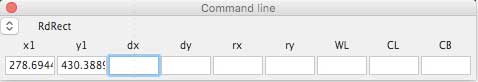 D-mode
After you have done your first click and started to drag to draw your rounded rectangle, hitting the D key will move the pallet to D-mode. In this mode dx and dy replace x2 and y2. dx is the distance travelled horizontally in the x-direction; dy is the distance travelled vertically in the y-direction. Thus dx will be the horizontal width of your rounded rectangle and dy will be the vertical height.
Enter the dx data and then tab to the dy box and enter that data. If you want to enter optional rx, ry, WL and/or CL and/or CB do so. Then hit ⏎ (Enter/Return) and let go the mouse.
To draw a rounded square enter dx only. Then hit ⏎ (Enter/Return) and let go the mouse. If you want to enter optional rx and/or ry and/or WL and/or CL and/or CB, tab through the dy box and enter the other data and then hit ⏎ (Enter/Return) and let go the mouse. You can also of course draw a rounded square by entering the same number for both dx and dy.
Tip: If your zero position is the top left corner of the screen (the default), then your start data will be positive numbers. If you have moved your zero point elsewhere, then both x-data and y-data can be positive or negative. Drawing from left to right will be x-positive; right to left will be x-negative. Similarly drawing from top to bottom will be y-positive and from bottom to top y-negative. If you have selected in Preferences for "Positive y upwards", then y-positive and y-negative will be reversed
Tip: You can move forwards and backwards along the boxes by using ⇥ (tab) and ⇧⇥ (shift-tab)