| RealCADD Cursors | |
|---|---|

|
Select cursor |

|
Object is selectable |

|
Select has found an endpoint |

|
Select has found a centre |

|
Select has found an intersection |

|
Select has found a surface (periphery) |

|
Select is in parallel mode |

|
Select can draw a parallel |

|
Lasso cursor |

|
Hand cursor |

|
Zoom cursor |

|
Text entry cursor |

|
Draw cursor |

|
Draw from centre cursor |

|
Draw by diameter cursor |

|
Draw by three points cursor |

|
Draw cursor has found an end point |

|
Draw cursor has found a centre |

|
Draw cursor has found an intersection |

|
Draw cursor has found a periphery |

|
Can draw a perpendicular |

|
Can draw a tangent |

|
Lines up horizontally |

|
Lines up vertically |

|
Lines up both horizontally & vertically |

|
Rotate or symmetry cursor |

|
Rotate cursor has found an endpoint |

|
Rotate cursor has found a centre |

|
Rotate cursor has found an intersection |

|
Cutting tool is active |
Initially RealCADD will open with a new Plan – "Untitled 1" – which will be displayed at the bottom of the Window menu. As more drawings are opened, they will add to the list. To move from one to another, simply click the one you want. The current drawing will be ticked.
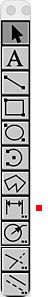 The Tools pallet accesses RealCADD's drawing, operating and modifying tools. When you mouse over the pallet, it expands to show the full range of tools available. If you have "Display helptags" enabled in Preferences, hovering over a tool for a moment will display its helptag. The basic keyboard shortcut for the row of tools is shown alongside the expanded tool pallet.
To select a specific tool click the appropriate tool row on the right-hand image and then scroll down to go to the details of how it works. The red dot  indicates which selection you are on. The descriptions are based on the standard Mac Click & Drag drawing mode. If you have selected Click & Click in Preferences, then there will be minor differences.
Tools with .. after them can be expanded to a fuller options menu by a double-click or an ⌥-click (option-click). Once a tool that has a further options menu has been selected, you can bring up the further options by hitting the space bar – this is very handy if you want to go on using the tool but merely want to change its action in some way.
All the tools have keyboard shortcuts as shown alongside the expanded tool pallet. Multiple entering the shortcut moves you along the horizontal row. A tool remains active until another tool is selected either by clicking on its icon or hitting its keyboard shortcut.
You can choose (in Preferences >> General) to have the Tools pallet expanded all the time by unchecking the "Tools" box.
With the Line, Rectangle, Oval and Arc tools, you draw the object approximately how you want it and then edit it in the Edit and Attributes pallets to get it exactly how you want it. The Edit pallet in particular is intimately bound up with drawing using the Tools and we will discuss it here along with each tool. Refer to Window >> Attributes for more details of that pallet.
Remember also that you can access all of, or your selection of, the tools by a right-click or a ⌃-left-click (control-left-click) anywhere in the drawing. The tools that are displayed are those chosen in Preferences >> "Tools" menu ... For a tool that has further options (those marked with double-dots in the Tools pallet), ⌥-right-click (option-right-click) or ⌃-⌥-left-click (control-option-left-click) as you select the tool will bring up the further options. Once you have selected the tool, if it is one that has further options, these can be accessed by hitting the space bar.
Tip: The screen version of the Tools pallet is only available when no object is selected. A right-click with an object selected will bring up the screen version of the Action menu.
With "Command Line" you draw an object (Line, Rectangle, Oval, Arc) and set its parameters on the fly as you draw. Refer to Window >> Command line.
Snap is also an important part of controlling how objects are drawn. Refer to Window >> Snap for details of how to set Snap up.
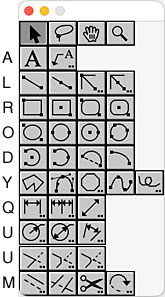
RealCADD cursors change to indicate many important aspects of using Tools; rather than endlessly discuss these changes in each section, they are listed in the table to the far right. Those that require Snap to be active are shown in green
Tip: The Surface cursor requires "Intersection" to be selected in the Snap pallet
Tip: Once you have one or more RealCADD files open, they will be displayed at the bottom of the Window menu and can be selected from there to change from one to another.
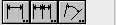 Back to top From left to right these are:
Single dimension: Keyboard shortcut Q.
If you have set your dimensioning preferences under RealCADD >> Preferences >> Dimensions, then you can simply proceed to dimension your drawing. If you want to change your preferences, either for the whole of this drawing, or for individual dimensions, the double-click or ⌥-click (option-click) on the single dimension tool and this will bring up a dimensions pane where you can change your preferences without going back to the RealCADD menu. Scroll down to find a discussion of this.
 Assuming that you don't want to make any changes, we show to the right dimensioning the side AB of the triangle ABC.
To start with make sure you have Snap (E) turned on, so that you can accurately pick up the end points of the line AB. We are going to draw the Red dimension.
Select the single dimension tool and hover over Point A until the cursor changes to the indicate it has found the end point, click the mouse button and, holding it down, drag over to Point B. When the cursor indicates that it has found the end point B, let go the mouse button and drag vertically to where you would like the dimension to be; click the mouse to complete the task. If you don't want to do any more dimensioning, hit the ⎋ (Esc) key to take you out of dimensioning and into the standard Select tool.
To draw the Green dimension, do exactly the same but this time, after you have found Point B, drag out horizontally until the dimension is where you want it and then click the mouse.
To draw the Blue dimension, again do exactly the same but this time, after you have found Point B, drag out roughly at 45º (going a little beyond the right of the triangle) until the witness lines change to be perpendicular to the line AB, then continue dragging until the dimension is where you want it and then click the mouse. Note that we checked the Rotate text box for this dimension so the dimension text is at the same angle as the dimension line. It's entirely a matter of choice and how you like your dimensioning to look.
Tip: Dimension Preferences have a menu item to select the position of the the dimension text relative to the dimension line (Above, Center, Below), this is not currently operative as of v. 4.50 and the dimension text will remain on top of (or to the left of) the dimension line. As of v.4.51b9, this preference is operational.
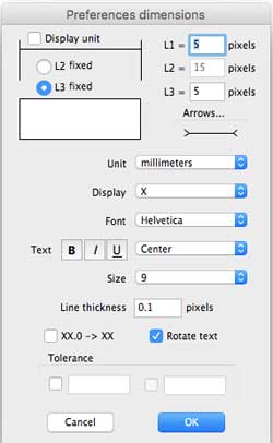 A double-click or an ⌥-click (option-click) on the tool will bring up the pane shown on the right.
This is similar to the Dimensions pane in RealCADD >> Preferences >> Dimensions, except that this pane only deals with linear dimensions, whereas the Preferences pane deals with both linear and angular.
Changes made here will cause the Preferences to change as well, and vice-versa. Remember that preferences are drawing-specific, so they are saved with each drawing.
Now let's look at the data on the Dimensions pane:
Display unit does exactly what it says: when the box is checked the unit of measurement will be displayed after the measurement as shown below.
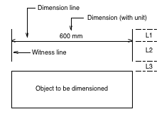 L1, L2 & L3. These can cause a little confusion, but in reality are very simple.
L1 is the distance the witness lines extend beyond the dimension line.
L2 is the distance the witness lines extend from the dimension line towards the object.
L3 is the distance the from the object to the start of the witness lines.
However you can only specify either L2 or L3. If you specify L2, then L3 will get greater the further you drag the dimension line from the object, and L2 will stay fixed at the length you specify. Conversely, if you specify L3, then L2 will get longer the further you drag the dimension line from the object, and L3 will stay fixed at the length you specify.
Probably the most common setting would be to specify L3 fixed and let L2 vary.
Arrows... controls what type of arrow the dimension line displays. To select this, mouse over the line with the arrows on and hold the mouse button down. The available arrow styles will appear. Still holding the mouse button down, move along the available arrow styles until you get to the one you want to use, and let go the mouse button go. The display will change to the arrow style you selected.
Unit selects the units from the drop-down menu to be used for linear dimensions.
Metric: Choose from kilometres, metres, centimetres and millimetres.
Pixels: Mostly used for drawings for screen use.
Customary US units: Choose from decimal feet, decimal inches, fractional feet and inches and fractional inches.
Display This sets the precision to which the linear dimensions are displayed. It doesn't affect the accuracy of the drawing, nor does it affect the display in the Edit pallet. The options will vary according to which units you have selected. Select from the drop-down menu.
Metric: From a whole number (X) up to six decimal places (X.XXXXXX). The last number will be rounded as usual: ≥.5 rounds up; <.5 rounds down.
Pixels: From a whole number (X) up to six decimal places (X.XXXXXX). The last number will be rounded.
Customary US units: With decimal feet and decimal inches, choose from a whole number (X) up to six decimal places (X.XXXXXX). The last number will be rounded. With fractional feet and inches or fractional inches, the selection runs from ½" to 1/512".
Font. Select the font to be used for dimensions from the drop-down menu. This doesn't affect the font used elsewhere on the drawing (this is selected in the Text pallet).
Text. The default for the dimension text is plain text. If you want your dimensions to be Bold, Italic or Underlined, select it here. You can select any one, or any mix of the three. The icons toggle, so to deselect, just click the appropriate icon a second time.
Position. This little drop-down menu controls the position of the dimension text relative to the dimension line. There is a choice of:
Center: Dimension text is centered in the dimension line.
Bottom: Dimension text is below the dimension line.
Size. Select the size of the font to be used for dimensions from the drop-down menu. You can select from eight preset font sizes, or Other... to specify a font size that is not included in the preset sizes. This doesn't affect the font size used elsewhere in the drawing (this is selected in the Text pallet).
Line thickness. Specify the thickness in pixels of the dimension and witness lines. You can enter any thickness – they don't necessarily have to be those that are preset in the Attributes pallet and it won't affect other line thicknesses elsewhere in the drawing.
XX.0 -> XX. Checking this box will cause a dimension that is a whole number to display as such, even though a display precision to one or more places of decimals has been selected. For example: You have selected to display dimensions to 3 places of decimals, but the object you are dimensioning is an exact whole number, your dimension will display as XX, rather than XX.000.
Rotate text. Check this box to have the measurement text display at the same angle as the dimension line. If left unchecked, dimension text will always be horizontal regardless of the angle of the dimension line.
Tolerance allows you to automatically add tolerance upper and lower limits to the dimensions. This is mostly used in engineering drawings.
 Multiple dimensions:
This enables you to do a continuous string of dimensions, rather than having to do each individually. The drawing to the right shows different segments of the line AD – AB, BC, and CD, individually dimensioned.
The process is very similar to single dimensions. Hover over A until the cursor indicates that it found the end point; click the mouse button and drag to Point B. Let go of the mouse button and drag away from AB until the dimension is where you want it. Click the mouse button. Move the mouse to the right and upwards to Point C – once over Point C and the cursor is showing an end point, click the mouse – which will draw dimension BC. Move the mouse to the right and upwards until Point D is found and then double-click the mouse button to complete.
The example described dimensions horizontally from left to right; you can equally well dimension from right to left, vertically and so on. The important thing is to finish with a double-click or else you will simply keep getting more and unwanted dimensions.
Double-clicking or ⌥-clicking (option-clicking) on the multiple dimension tool brings up exactly the same preferences pane as for a single dimension.
 Angular dimensions:
This works in a very similar way to linear single dimensions. Our triangle ABC is shown again to the right. This time we are going to dimension the angle ACB
When you click the tool, you get the Select cursor instead of the Draw cursor. We are going to draw the included angle (shown in Red).
You don't need to find the end point of the lines making up the angle – just move the cursor until it changes to the Object is Selectable cursor – hovering over line CA in our triangle. Click the mouse and, holding the mouse button down, move across to the second line (CB) and when the cursor changes again to the Object is Selectable cursor, drag to where you want the dimension and let go the mouse.
If you drag above Point C of the triangle you will get the external angle, shown in (shown in Green). And if you drag beyond the line AB, you will get the internal angle, with added witness lines (shown in Blue).
Double-clicking or ⌥-clicking (option-clicking) on the angular dimension tool brings up a very similar preferences pane as for a single dimension. The only differences are:
Unit: Choose from Radians, Degrees or Grades.
Display: Choose from a variety of decimal places; or degrees and minutes; or degrees, minutes and seconds.
Rotate text: Not available – dimension text is always horizontal.
Tip: In RealCADD versions 4.62 and below, the angular dimension tool will not measure angles of 5º or less. By the same token, it will not measure an external angle of 355º or more. In the beta version 4.63b1, the minimum dimensionable angle is reduced to 1º.
Tip: All dimensions are really just groups and can be ungrouped (⌘U). They can then me modified if you wish to.